


Updated October 28, 2021.
One of the most important steps in designing and deploying a visibility platform is determining where and how to collect packets from across your computing environment. No matter how great your security or performance tools, if you don’t provide them with the right packets, they won’t be able to effectively do their job monitoring and protecting your infrastructure. As a visibility platform is designed from the ground up to collect packets of interest from your entire computing environment, filter, transform, and then deliver them to the tools that will process them.
This first step in the design process builds a solid foundation for the Traffic Visibility Fabric. In this article we will explore the process of identifying the traffic of interest and figuring out where in your network you can collect those packets.
Which Packets Do I Need to Collect?
It really depends on the tools you are using to monitor and secure your computing environment. These applications will dictate what traffic you need to collect. If you have tools that are analyzing packets to report on application or network performance, or troubleshooting, you will likely wish to collect data on those uplinks from the network access to distribution layer or perhaps from the distribution to the core. The goal is to see the packets from the end users to the servers they commonly access either in your corporate data center or on the Internet and those packets typically traverse these uplinks.[i]
For security tools, the critical parts of your computing environment are the links to the Internet, the data center core to aggregation layer links within your data center, the virtual switches in your private cloud and the packets flowing to or from your servers in the public cloud. There are many different types of security tools available in the marketplace, and each has specific data collection preferences. Some tools focus on data loss prevention (DLP), intrusion and malware detection and protection; others on application, Web, database, and file security. For example, if you are concerned about malware and intrusion protection or perhaps DLP, you should collect data from your Internet connections and data center links containing packets destined for the file and mail servers. If you are concerned about malicious activity within your data center (DLP, IDS, data exfiltration), you will want to monitor east-west (server to server) traffic by collecting packets from the links that carry server-to-server traffic as well as the virtual switches within your private cloud. As the saying goes, you can’t protect against threats that you can’t see.
Though it is beyond the scope of this article to discuss the specific data needs of each type of security tool, I advise learning the data needs of your tools to ensure that you are collecting the packets that matter. To maximize their effectiveness and protect your network from performance problems or security threats, it is best to collect and deliver every packet a tool needs to see—and avoid sending irrelevant packets, which will increase the bandwidth required on the physical network interface and add extra processor cycles to filter out extraneous data.
Collecting Packets: The Physical Layer
Customers often ask, “Where should I deploy my TAPs?” Typically, only a select few within your organization will have the answer. In fact, it’s a relatively rare occurrence that those who own the tools have a deep knowledge of the network architecture they are tasked with monitoring. The security team (and perhaps other teams that have tools that wish to see packets) knows what type of data their tools need to see, and the network team knows where the packets are flowing within their network. Close coordination between these two groups is key to effectively deploying a visibility platform.
Once you have defined the data collection requirements of the tools, you need to select where in your computing environment this data can be obtained. You will need a network drawing that includes information on both the physical connections between networking equipment as well as the logical path of the packets. Typically such a drawing doesn’t exist, there is just simply too much information to fit it all into a single drawing. The logical drawing of the computing environment that shows servers, data centers, end-user VLANs, and Internet access points, as well as how they connect to each other through firewall, and routing functions. This logical view of the computing environment must then be laid on top of the physical network drawing such that it clearly shows the path packets take from point A to point B. 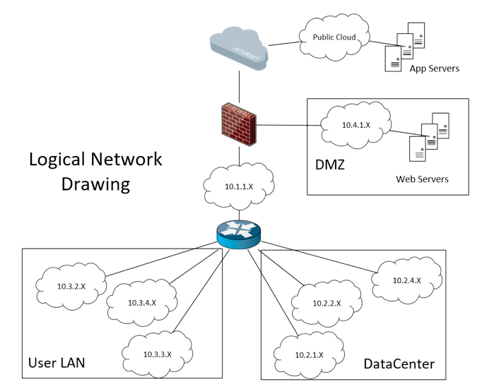
The physical network drawing should include the physical medium for each connection (copper, single mode/multimode fiber) and the speeds of each link (10M/100M/1G/10G/40G/100G etc). This information will be used to select the right TAPs to deploy within your network.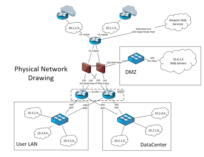
In addition to traditional locations (e.g., Local Area Network, Data Center, DMZ), packets of interest can be found in a virtual server environment or a public cloud service such as Amazon Web Services (AWS).
To provide the most benefit, any tools that work by analyzing packets need to collect all the packets they need from the computing environment which they monitor. In order to be fiscally responsible, you will want to identify the smallest number of physical network cables that achieve this goal and install a Test Access Point (TAP) on these links. A TAP is normally a relatively simple piece of hardware that is installed on the cable that connects two network devices and it generates a copy of all information that travels between the two network devices.
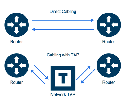
It is best to use TAPs 99% of the time, but if you cannot afford to TAP every link connected to a given distribution switch, then a copy of the traffic may be obtained by configuring a SPAN/Mirror port on a switch or router within a logical data path where traffic of interest is flowing. The golden rule of a visibility platform is: TAP where you can, SPAN if you must. SPANs and TAPs are not created equal, so please check out this “SPAN Port or TAP?” white paper and have a look at this TAP vs. SPAN infographic for detailed information on the pros and cons of TAPs and SPANs.
Quantity and Quality
Packet collection is probably the most important part of designing your visibility platform. If you collect the wrong packets, collect too few packets by neglecting a portion of your computing environment, or lose packets during a denial of service attack or other performance-impacting situation in your network, tool performance will suffer. Most security tools depend on seeing the entire conversation to locate and isolate threats and if even one packet of an application session is missing, the whole transaction is discarded. Packets matter. Build your visibility network on a solid foundation. Plan out your ideal packet collection schema, implement what you are able, and document the weak points in your data collection plan.
Your goal of creating a platform that enhances monitoring of your computing environment requires proper design, implementation, and maintenance. I have seen many deployments of fantastic tools that are connected to a single SPAN port off a core router. In my opinion this approach does a disservice to the tool vendor who created a great product and to the customer who expected a great product to meet the business need for which they purchased it.
If you are reading this article, you are probably unhappy with the status quo and are looking for a more reliable, predictable, and scalable approach to monitor and secure your data in motion. The Gigamon Visibility Platform will give you the ability to achieve this goal. Now, go forth and see what matters.
[i] Please contact your network performance and security tools vendors for further information on the best place to collect packets to help their tools provide you with the performance and security data you desire.