


Understanding Network TAPs, Part 2: Passive TAPs vs. Active TAPs
In this second part of our ongoing series on Understanding Network TAPs, we discuss passive TAPs and active TAPs. Learn about these two main types of TAPs, along with the advantages and disadvantages of both.
Welcome to the second entry in a series of blog posts inspired by the recent Gigamon TAP whitepaper, “Understanding Network TAPs — The First Step to Visibility.” In Part 1 we briefly examined network TAPs (Test Access Points) and SPANs (Switch Port Analyzers), including their relative strengths and use cases.
This time? It’s all about TAPs, and the factors that differentiate the two major types: passive TAPs and active TAPs. Let’s dig in.
Passive TAP Basics
Passive network TAPs are so called because they don’t require power to operate. These devices contain an optical splitter that creates a copy of the signal as it passes through — and this applies to fiber TAPs and 10/100M copper network TAPs. With no moving parts, they’re highly reliable, and do not require configuration. Passive TAPs are unidirectional — that is, they only send traffic, never receive it — so a passive, 10Gb TAP equipped with two ports could pass through 20Gb of data. Sharing the load between the two eliminates the chance of oversubscribing just one.
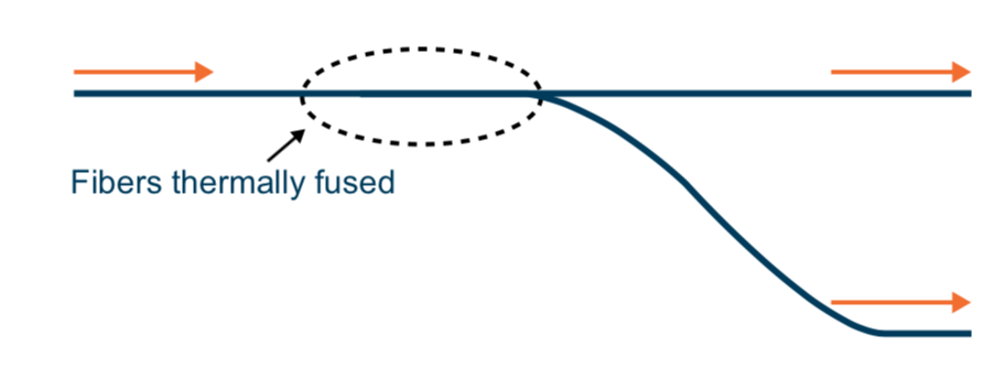
The types of optical splitters inside these TAPs can greatly affect their functionality and use cases. A simple splitting method called Fused Biconical Taper melts two cables together in order to funnel a portion of the light signal off to a monitoring output. These splits are low-cost and well-suited to lower-speed infrastructure.
The other major type of splitter uses Thin Film technology. In essence, a clear window in the cable allows most light to pass through, but diverts (reflects) enough of the photons to feed a monitor port. This technique leads to a lower packet-loss rate in higher-speed links.
Other Considerations
Split ratio: Regardless of the type of splitter used, part of the light signal will be diverted for inspection, which weakens the portion that continues onward. The proportion of the network percentage to the monitor percentage is the split ratio. A common ratio for 1Gb short-range links is 70/30, and the network percentage is often higher to reduce the risk of dropping traffic. Different network speeds dictate different split ratios, and today 50/50 is a common ratio for modern networks with adequate light levels. (See the whitepaper for a deeper dive into the considerations at work here.)
Power budgets and light loss comprise another major area of concern. Cable light levels degrade fairly quickly, resulting in optical power loss. All passive network TAPs divert a portion of light without boosting the signal, so it’s important to understand exactly how much light will be lost through the wire over a given run of network.
Briefly, the power budget is the difference between the transmitter power output and the receiver sensitivity. You can calculate, as explained in the whitepaper, statistics like the power budget, cable attenuation, connection loss and power margin to determine if a passive TAP can function at a given point in a network’s infrastructure. If the light loss is too great, that’s one of the scenarios where an active TAP is called for.
Active TAPs
Active TAPs, of course, require electricity to do their jobs. Because they retransmit all signals, split ratio is no longer a factor. However, during a power loss an active TAP can be a point of failure, so passive network TAPs are generally preferred. Here are a few scenarios where an active TAP makes sense:
- Locations where the light levels are too low to use a splitter; regeneration provides a viable solution
- Copper infrastructures where electricity is used to move electrons (instead of photons)
- Signal conversions — since an active TAP regenerates the signal anyway, it can also be designed to create a signal of a different type (such as 10Gb SR converted to 10Gb LR)
- SFP-based links that cannot otherwise be broken (such as TwinAX cabling) — regeneration works here as well
Finally, the more advanced active TAPs may have backup batteries to extend usage during power failures, as well as graceful failover features that will allow network traffic to pass through, even as the TAP’s monitoring output ceases.
Read the Full Whitepaper for More
The third and final blog post in this series will explore some TAP best practices. If you’d like more now you can check out the full Gigamon TAP whitepaper here (PDF). Or visit the Gigamon Network TAPs site to learn how Gigamon products leverage TAPs to provide excellent visibility into network traffic. Until next time.
Further Reading:
- “So You Want a Network Packet Broker — Remember These Nine Best Practices“
- “The Art of Scrying — How Network Visibility Helps Enterprises ‘See’“
- “What to Tap Virtually, and What Not to Tap Virtually? That Is the Next Question!“
Featured Webinars
Hear from our experts on the latest trends and best practices to optimize your network visibility and analysis.

CONTINUE THE DISCUSSION
People are talking about this in the Gigamon Community’s Networking group.
Share your thoughts today